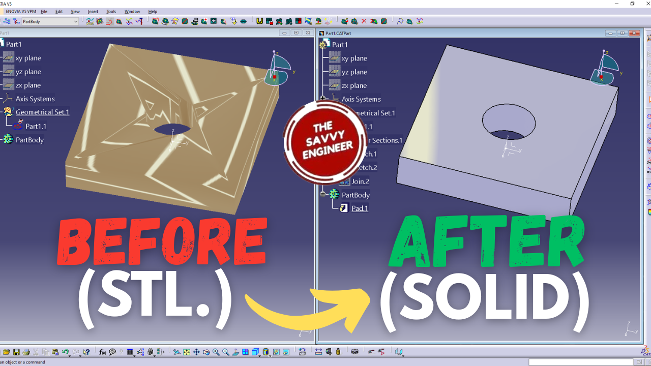


Learning how to convert an STL model to a solid body in CATIA for reverse engineering is essential for transforming 3D scan data into editable and manufacturable designs. STL files only contain mesh geometry, which limits modification and precision. By converting them into solid models, you can easily analyze, refine, and redesign parts using CATIA’s parametric tools.
This process is vital when recreating existing components without original CAD files, ensuring accuracy and compatibility with simulation or manufacturing workflows. Mastering this skill enhances your ability to turn real-world objects into professional, fully functional digital models for engineering applications.
First, go to Start, Shape, then digitized shape editor.
Check the ‘enable hybrid design‘ and the ‘create a geometrical set‘ options, then click on OK.
Click on the ‘import‘ command.
Click on the ‘…‘ command to search for the STL file. you can click here to download this stl file which i created in CATIA.
Once, you downloaded the STL file, open it in the digitized shape editor workbench.
Click on apply, then you will see the stl file in the workbench. Then click on OK.
Click on the Planar sections command.
Select the Element field. Then click on the Part1.1 model.
For the reference, click on the flip to (XY) command. Click on Apply, then OK.
Go to Part1.1, do right-click, then click on hide.
You will get a rectangle and circle sketches, see image below.
Go to Start, Shape, then click on Quick Surface Reconstruction.
Click on the ‘Sketch from Scan’ command.
Select the ‘Element’ field, then click on the ‘planar sections1.1‘.
Click on save, then OK.
Do right-click on the planar sections.1, then click on hide.
Click on the join command, select the sketch.1 and the sketch.2. Uncheck the ‘check connexity‘ and ‘check manifold‘ options, then click on OK.
Go to Start, mechanical design, then click on the part design workbench.
Go to Pad, then if you get this warning dialog box, just click on OK. in this case, the join sketch will be saved under the geometrical set, and the extrusion will be saved under the part body.
In the profile/surface field, select the join feature. Next, check the mirrored extent command, then click on OK.
Yes! You did it! Good Job! This is how it looks like to create a solid body from an stl model.

You cannot copy content of this page
