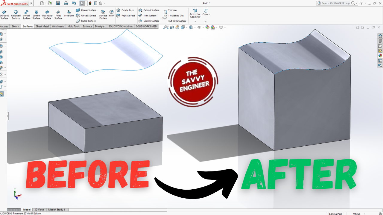


Learning how to extrude a part face up to a surface in SolidWorks is essential for achieving precise and adaptable designs. This tool lets you extend a feature until it meets a target surface, ensuring perfect alignment with curved or complex geometry. It improves accuracy, reduces manual adjustments, and allows automatic updates when the reference surface changes.
This technique also enhances parametric modeling efficiency, making your designs smarter and easier to modify. By mastering it, you gain greater control over part creation and develop the skills needed for advanced, professional-level modeling in engineering and product design.
Go to the top Plane, click normal to, then click sketch.
Go to the center rectangle command, create a rectangle starting from the point of the axis.
Go to the smart dimension command, use it to add 100mm for the length and 100mm too for the width. Click OK, then exit the workbench.
Go to features, then extruded boss/base.
Add 30mm to the extrusion, then click on OK.
Go to the front plane, click normal to, then click on sketch.
Go to the spline command, draw a new spline like this one, see image below. Then click on OK.
Hold the Ctrl key, select the point in the extremity of the spline, then select the edge of the extrusion. Now, go to the left side of the screen, you will find the coincident option, click on it. Then, click on OK.
Now, repeat the last step to the other extremity of the spline.
Go to the surfaces tab, then click on extruded surface.
Add 100mm to the first direction, add 100mm too to the second direction, then click on OK.
Go to the Replace face command.
Select the target faces for replacement field, then click on the top face of the extrusion. For the replacement surface, click on the surface, then click on OK.
The final result of this tutorial should look like this, see image below.
Good Work! You did it!


You cannot copy content of this page
