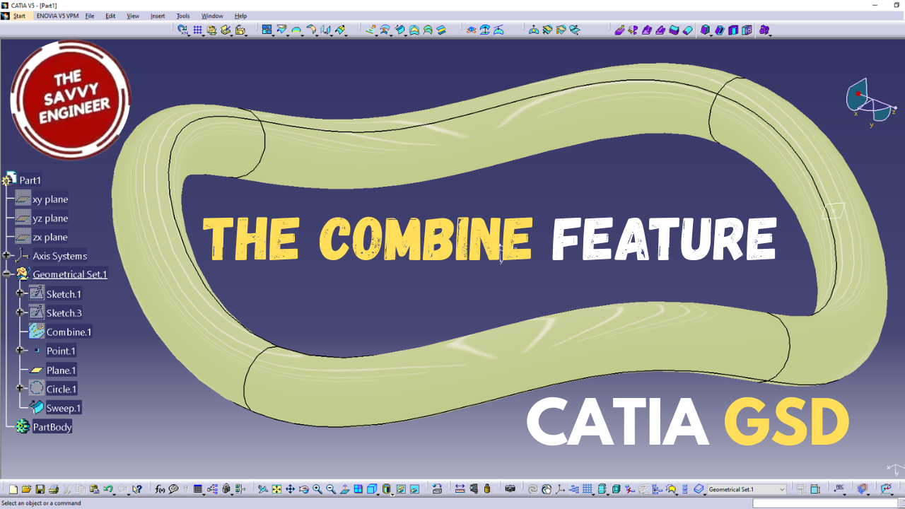


The CATIA Generative Shape Design (GSD) workbench is a powerful environment designed for creating complex, high-quality surfaces, and one of its foundational tasks is combining two sketches to build smooth and controlled geometry. For beginners, this process demonstrates how curves, constraints, and surface tools interact to form the basis of advanced models. When working in GSD, sketches serve as the guiding framework for generating surfaces or blended shapes. By combining two sketches, you can transition from simple 2D definitions to refined 3D forms, making the workflow essential for designing products such as automotive bodies, consumer products, and aerodynamic components.
The workbench provides several tools—such as Loft, Sweep, and Multi-section Surface—that use multiple sketches as input. These commands allow you to merge profiles, connect edges, and shape surfaces with precision. For example, using the Loft tool, you can create a smooth surface between two profiles, while the Sweep tool can generate a surface based on a guide curve and a profile. This flexibility allows designers to adapt the model to aesthetic requirements or engineering constraints.
Combining sketches in GSD also teaches critical concepts like continuity, curvature control, and surface quality. CATIA enables you to manage these aspects with advanced visualization tools that evaluate the smoothness and transitions between combined elements. This capability is essential when designing parts that require consistent aerodynamic or ergonomic properties.
Learning to combine sketches in the GSD workbench helps users move beyond basic solid modeling into more sophisticated surface design. It builds confidence in handling complex shapes, encourages creativity, and prepares designers for real-world projects where precision and surface integrity are crucial. This introduction provides a strong foundation for exploring more advanced CATIA surfacing features.
Second, click on the (XY) Plane, then go to Sketch.
Select the Spline command, then draw a spline composed by five points, see the image below.
Click on the constraint command to add a 50mm dimension between the Y–axis and the extremity of the spline.
Add another 50mm dimension on the other side of the spline, see the image below.
Go to the constraint command to add a 10mm dimension between the top point of the spline and the X-Axis, add the same dimension between the other point and the X-Axis.
Exit the Sketcher workbench.
Next, exit the sketcher Product.
Go to Insert, Wireframe, then click on the combine command.
For the First curve, click the sketch.1, then sketch.2 for the second curve. Click on OK.
Hide the first and the second sketches.
Add a Point on the Curve.
Go to Plane, then select the normal to curve plane type.
In the Curve Field, select the Combine Feature. In the Point Field, select the Point.1.
Click on the Circle command, we are going to use the whole circle option.
For the Center, Click on the Point.1, then select the plane.1 as a support. Change the radius value from 20mm to 5mm, then click OK.
For the Center, Click on the Point.1, then select the plane.1 as a support. Change the radius value from 20mm to 5mm, then click OK.
Go to the swept surface command, select the circle.1 as a profile, then select the combine.1 as a guide curve. Next, Click on OK.
You will get a Result like this, see the image below. Good Job!

You cannot copy content of this page
