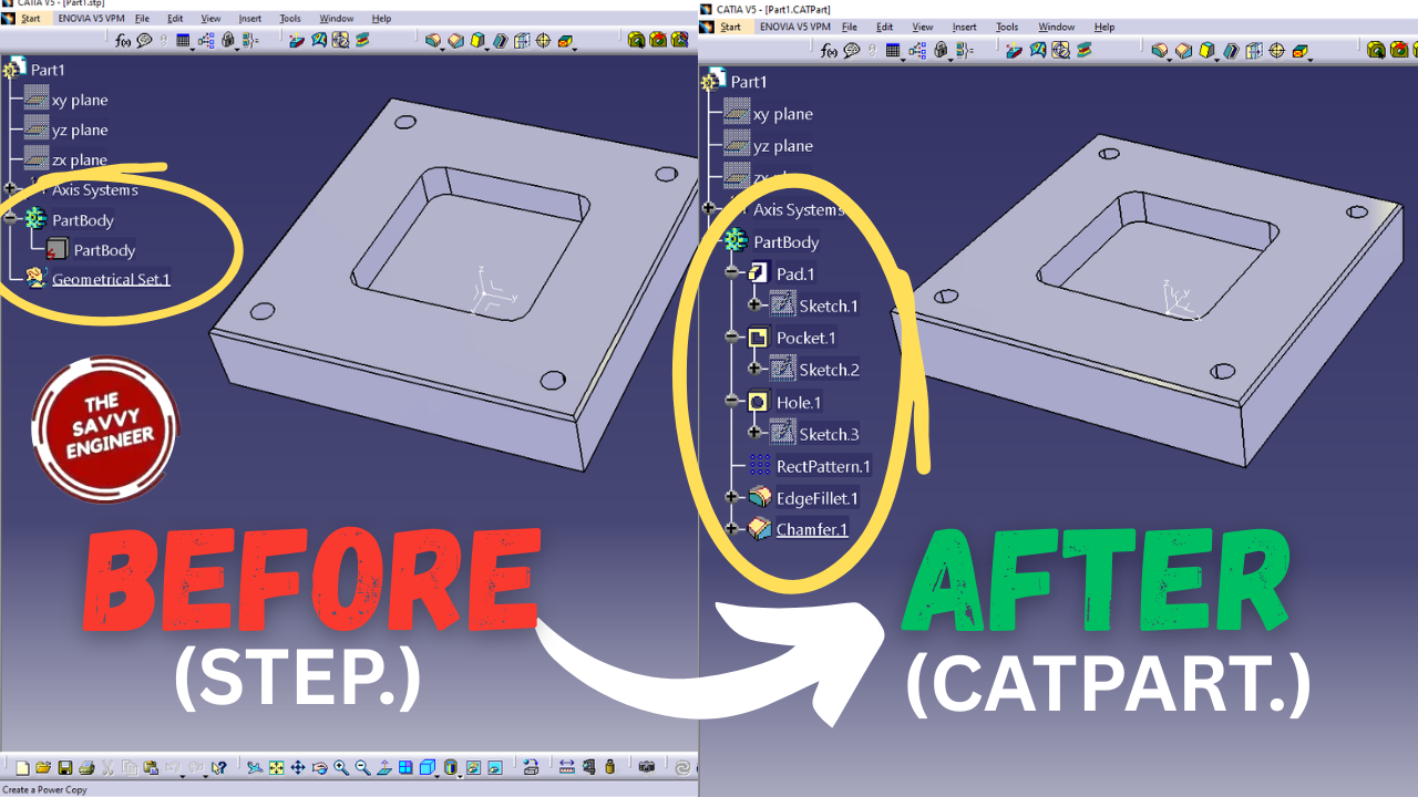


Learning how to convert a STEP file into a CATPart in CATIA is essential for anyone working with 3D design and engineering projects. This skill allows you to easily import and edit models created in other CAD software, ensuring smooth collaboration across different platforms. By mastering this conversion process, you can modify, analyze, or optimize external parts directly within CATIA’s environment. It also saves time and prevents data loss during file translation. Understanding this workflow is crucial for engineers, designers, and manufacturers who regularly exchange files in multi-software design teams or global engineering environments.
First, we are going to design this simple 3D model in the part design workbench of catia, then save it as a STEP File. next we are going to open the same step file in catia , then we will use my secret command in the part design workbench to extract the features so that we can use them to modily the piece and save it as a new design, ok!
Click Start, go to mechanical design, then click part design workbench.
Check the enable hybrid design option, then click ok.
Click the (XY) Plane, then go to Sketch.
Click the (+) sign of the part body tree to see the future features, then go to the centered rectangle command.
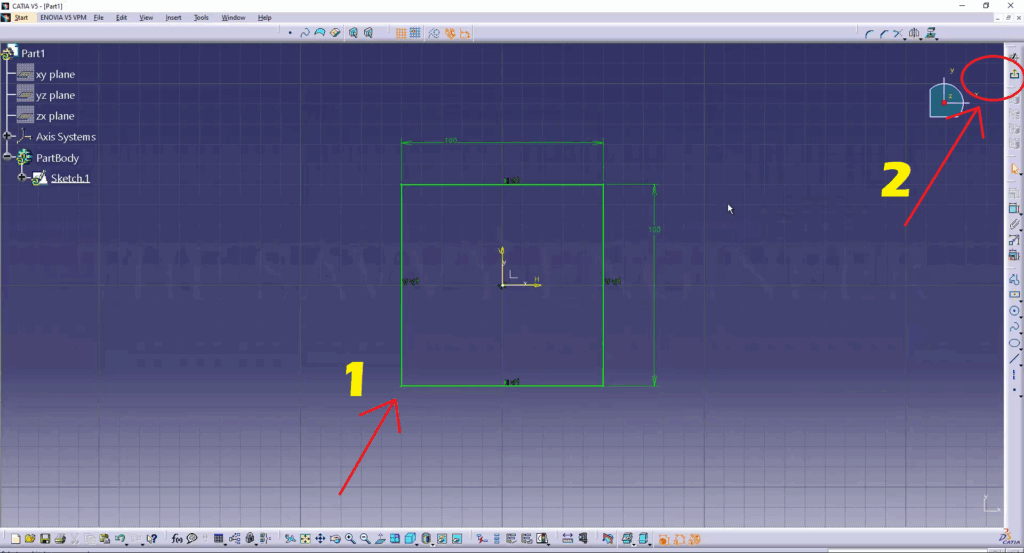
Create a Rectangle starting from the center of the Axis, use the constraint command to add the first 100mm dimension.
Add the other 100mm dimension. make sure that the rectangle looks like this, see image below. Next, exit the sketcher workbench.

Click the Pad Command, add 20mm value, then click OK.
Click the Top Face of the Extrusion, then go to sketch.
go to the centered rectangle command, then Create a rectangle starting from the center of the axis.
Make sure you add 100mm for both dimensions, the length and the width, then exit the sketcher workbench.
Now, you go to the Pocket Command, then you create a pocket of 10mm depth, then you click OK.
Now, You go to the Edge Fillet command, Add 5mm in the radius field, then select all the four edges of the pocket, then click OK.
Now, you go to the Chamfer Command, then select the four edges of the top face, add 1mm in the length1 Field, and 45deg for the angle. Click OK.
Click the top face of the Part, then go to the Hole Command. Next, click the positioning sketch Option.
Go to the constraint command, then Add 10mm between the center of the circle and the edges, see image below.
Now, Exit the Sketcher Workbench, then add 6mm in the Diameter Field and change the hole type from blind into up to next, then click OK.
Now, Exit the Sketcher Workbench, then add 6mm in the Diameter Field and change the hole type from blind to up to next, then click OK.
Do one left click on the hole feature, then go and click on the rectangular pattern command. In the first direction tab, add the value 2 in the instances field, and 80mm in the spacing field. for the reference direction, select the top face of the part.
In the second direction tab, add the same values, 2 in the instances field, and 80mm in the spacing field. Then, click OK.
Now, go to File, then click Save As.
Now, go to File, then click Save As.
You can add a name to the piece, then select the STP. type for the file.
Click File, then go to open.
Select the STP. file, then click Open.
Click the (+) sign of the part body tree.
Select the part body then do right click, click on the ‘define in work object‘ option.
Click on the Manual Feature Recognition, then click on the automatic tab.
Check the Local Feature recognition option, then check the All Option too.
First, select the Top face, then the bottom face of the Piece.
Select all four Side Faces, the Walls.
Select the Bottom of the Pocket, then its Walls.
Select the Chamfers.
Select the four Holes.
the part body needs to have a pink color, then click ok.
You will get all the features needed to create this piece. Go to the last feature, do right-click then select the define in work object option.
Yes! You did it! Good Job! Now, You can see all the features of the piece, you can use each one of them, modify it then save your design as a CATPART File!


You cannot copy content of this page
